Some of the issues you may face when using Niryo One are due to a mistake during the assembly phase. Also, if you’re assembling the robot by yourself, you’ll have to be careful about some points.
You’ll find below a list of possible issues that can happen due to an assembly mistake.
!!! Before modifying anything on the robot, make sure to power it off and unplug the power adapter !!!
First of all, make sure that you have correctly plugged the power adapter, and switched the power button on.
All the PCBs were tested before shipping. Any problem about the LED is probably coming from a faulty connection between the Raspberry Pi and the Panel Connector.
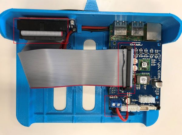
Ensure that the Niryo Raspberry Pi Shield is correctly plugged on the Raspberry Pi 3, and that the JTAG-20 (19 grey cables and 1 red cable) is correctly plugged, as shown below :
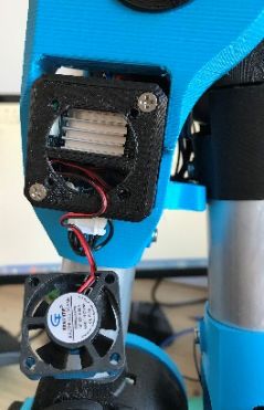
Place your robot on its side and locate the fan inside the base.
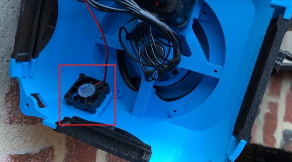
Make sure that the fan cable is correctly plugged to one of the fan connector on the Niryo Raspberry Pi Shield.
If the fan is too noisy, this is probably because it is not correctly mounted, and thus has more vibrations. Make sure that the fan is 100% fixed.
If you can’t solve this issue, it’s possible that the fan itself is broken. Try to replace the fan by a new one and test again.
There are 2 possibilities here.
1. Check that the 4-wires connector is correctly plugged to the motor and that the 4 wires cable near the motor is loose enough so the axis can move without pulling on the connector.
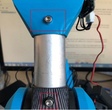
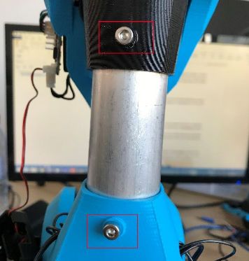
2. When tightening the screws to assemble the aluminum tubes with 3D printed blue parts, be careful not to cut some wires which are going through the tubes.
If needed, you can use a multimeter to locate broken cables.
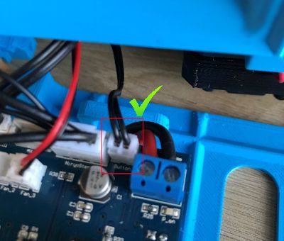
Check that the button connector is correctly plugged to the Niryo Raspberry Pi Shield.
You should not have any problem about that when assembling Niryo One because we are assembling and testing all the Niryo Stepper ourselves.
In case you are unmounting and mounting again the Niryo Stepper by yourself, please pay attention to the following.
If you choose a too long screw (23mm on the photo) to tighten the fan on the back of the stepper motor, the screw will touch one of the PCB capacitance, which will be destroyed.
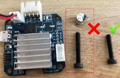
Ensure that you use a shorter screw (19mm max) so it doesn’t touch the capacitance.
If you have already destroyed the capacitance, take it out and replace it with a new one. Here’s the reference of the component.
If you start an auto calibration and the calibration doesn’t seem to work, here are some guides to debug and fix your robot (in the order):