We’ve improved the hardware again. After reading this post, check out this one to see the new stuff.
Hello everyone,
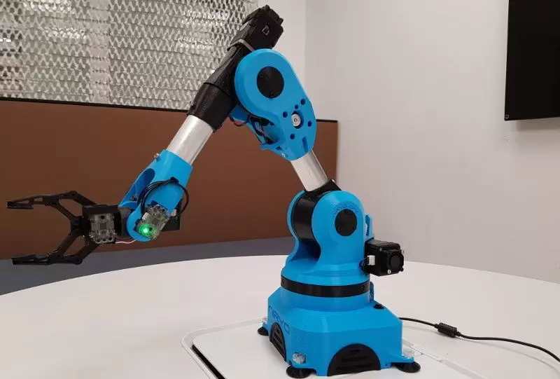
We’re back with many good news ! We’ve worked hard this summer to improve Niryo One in many ways. Time for you to catch up with us!
Back in April 2017 we found that the global hardware architecture was not so stable, and some huge improvements could be made on the motors.
We decided to change completely some parts of the robot, to make it more stable, robust, and increase the number of functionalities.
So… What has changed ? Let’s see step by step all the new stuff :
New functionalities and improvements
Before we start explaining some of the technical stuff, let’s see what improvements you can get, in terms of usability:
- Trajectories are smoother and more precise.
- Niryo One is globally much more stable and robust.
- The robot is much easier to assemble, with less wires, and better cable connection.
- Niryo One will stop if an obstacle is on its way, or if the load is too heavy. After being calibrated, if the robot missed some steps (ex : load too heavy), the trajectory execution will stop and you will be able to start it again.
- Auto calibration : Niryo One will be able to calibrate itself each time you turn it on. You can save a position sequence, and replay it exactly the same way every time.
- You can shutdown the robot and switch it to Wi-Fi Hotspot mode, simply by pressing the integrated button.
- A LED on the back will give you info about the robot state.
- A panel connector will allow you to use other devices (like sensors, digital I/O) along with Niryo One.
- …
OK, now let’s dive into the technical details ! We’ll give you here an overview of all the different parts, more detailed info will be available in the future.
A brand new hardware architecture
Here’s a before/after picture of the inside :
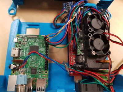
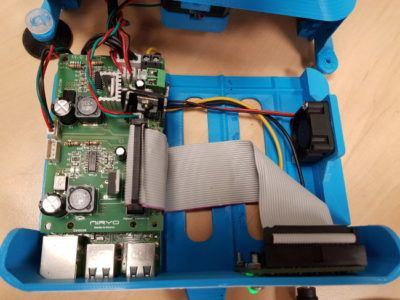
Before
After
We used to control the motors directly from an Arduino Mega board, with a RAMPS 1.4 shield. This combination really fits the 3D printing world (for example with RepRap 3D printers), but is not so well suited for a 6 axis robotic arm.
With this previous architecture we had many long wires for each of the motors, which is not great, and the control was somewhat limited. All motors were controlled from the same board. We had problems with stepper driver overheat inside the box, and the communication between the Arduino Mega and Raspberry Pi 3 (I2C) was not the best we could have.
From those problems and limitations, we discovered many ways of improvements. We also really wanted to make Niryo One as close as possible from a real industrial robot.
A brand new hardware architecture was needed, and we decided to take action, seeing all the benefits you could get with it.
We’ll now show you step by step all the new cool stuff.
Dynamixel motors
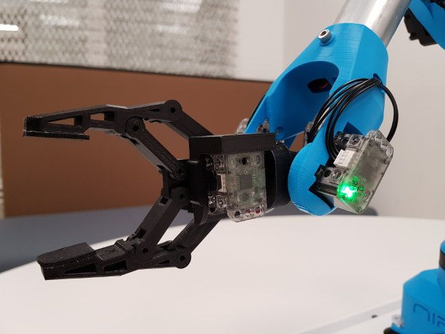
We replaced basic servo motors with Dynamixel XL-320 motors (for axis 5 and 6), much better and much clever motors. Less wires to deal with, a better stability, position feedback, and a nice feature for grippers.
All Niryo grippers equipped with Dynamixel motors can grab any object, without having to know the object width, thanks to the load feedback.
This also increases the range of axis 5 and 6, from 180° to almost 300°.
Stepper motors
Stepper motors are the same, but the way we control them is totally different.
We used to have all stepper motors (axis 1 to 4) directly powered and controlled from an Arduino Mega + RAMPS 1.4 shield.
Now, each stepper has a custom Arduino compatible board attached on its back. The board has the same microcontroller as the Arduino M0 board (SAMD21). This microcontroller is more powerful and has better communication features than Arduino Uno, for example.
This new Niryo custom board has a microcontroller, a motor driver, and a magnetic sensor (AS5600). Thus each motor is independently controlled, with an internal controller, which is much like a real industrial robot motor.
We’ve also replaced the 2 motors of axis 2 with one longer motor.
A new top for the Raspberry Pi 3 board
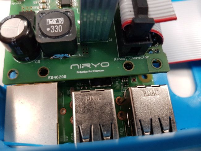
After hearing about so many changes, you might be nervous about the Raspberry Pi 3 board. Don’t worry, it’s still there !
We created a Niryo custom shield for the Raspberry Pi 3 board. This shield, and the Arduino compatible boards on the stepper motors, now replace the previous Arduino MEGA + RAMPS 1.4 combination.
The shield has mainly two purposes :
- Getting power from the source, and powering all the motors and electrical components
- Communication between Raspberry Pi 3, and all the motors, sensors, actuators.
The Dynamixel TTL bus is directly plugged on the shield, as well as the CAN bus cable (see next point). We are using Raspberry Pi 3 GPIOs to communicate with those buses.
As you can see, we now have a direct control over all the components from the Raspberry Pi 3.
An improved communication with motors
Before, each motor had its own set of wires, and the control was opened-loop. To make it closed-loop we had to add another set of wires for the sensors.
Now, there is a single set of chained wires for all the Dynamixel motors, and another one for all stepper motors. This cable includes power and communication in two directions. Only two cables inside the robotic arm!
Dynamixel motors use TTL half duplex communication, with a 3 wires connector which is chained through all motors.
To power up and communicate with the new Niryo custom boards on top of all stepper motors, we’ve decided to use CAN communication. If you don’t know about CAN, this is a very stable communication protocol, which is also used in automotive and health applications.
Each stepper motor has a unique identifier (1 to 4) on the CAN bus, and can receive commands from Raspberry Pi 3, but also send useful data back (current encoder position, driver temperature, …).
A panel connector for more DIY projects
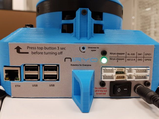
We know that you love DIY projects, so we’ve added a panel connector on the back of the robot. This panel is connected to many Raspberry Pi GPIOs.
You can add a new device on the CAN bus, add some Dynamixel motors. If you want to handle lower level components, you can also use the digital GPIOs.
We’ll develop some parts of software (early 2018) to allow you to use those inputs/outputs easily, from ROS communications to an application on the Niryo desktop software.
…desktop software ?
This topic is not hardware-related, but is a part in the many improvements we’ve made. We chose to develop a desktop software, instead of an application running in a browser.
Basically, this is exactly the same thing, but we could add more functionality which are not available on a browser like Firefox or Chrome. You will also be able to use it while not being connected to the Internet, which is a must-have for some applications.
This software will be available for Windows, Mac and Linux, and will not require any installation. Just download it and run it! We’ll give more info later on that subject.
Easier to assemble
Less wires always means less pain to assemble the robot, and less connection problems. Speaking of connections, we’ve improved the cable so that you can easily plug all wires in the right place, without any problem.
The inside of Niryo One’s base is also less crowded. Once the arm is assembled, you’ll just have to fix the Raspberry Pi 3 board, add the Niryo custom shield, plug the power and wires, that’s it ! (This is already done for you in the Fully Assembled package)
Niryo One now includes ROS-Industrial full stack
In a previous post we’ve explained how we use Robot Operating System (ROS) on the Raspberry Pi 3 to control the robot.
Thanks to the new hardware architecture, we are now able to send commands to motors, and receive data, all that at a high speed, with almost real-time constraints. What does it mean ? We can now use more advanced ROS controllers on the robot, which will always adapt the command depending on the data received.
We’ve added ros_control to the stack of ROS packages used on Niryo One. The robot has now a ROS-Industrial full stack :
- URDF for robot description
- Moveit! for motion planning
- ros_control with a joint trajectory controller (quintic spline interpolation)
- Closed-loop hardware interface between motors and ros_control
- Plus all the other Niryo ROS packages!
Roadmap and delivery planning
We have now finished the core development of Niryo One, and are ready to start production! We plan to start shipping all Kickstarter rewards and other pre-orders from November 2017. Niryo One will be on normal sale from February-March 2018.
We’ll also provide you with all the required documentation : how-to guides, assembly manual, ….
Open source files (STL and source code) will be released soon, mainly on github. Be sure to follow our github account so you don’t miss that.
Niryo desktop software will be available after the first shipments.
We’ll keep improving the software on the robot, and the applications around it. Many updates will be available to keep improving Niryo One over the next months. We also count on you to give us your feedback, and why not, contribute with the open source community!
Niryo One has now a hardware and software architecture really, really close to a full industrial robot.
We are confident that you can use Niryo One to learn and teach robotics, do some professional training, and start small assembly lines on your own.
Vous pouvez désormais commander Niryo One !